Intermittent Rub in Steam Turbine Due to Carbonized Oil Seal
- NK
- Oct 10, 2023
- 4 min read
A back-pressure steam turbine that drives a 12 MW generator, experienced intermittent spikes in shaft vibration amplitudes at the low-pressure (LP) bearing, especially when the power output exceeded 10 MW. These spikes sometimes caused the unit trip, resulting in limited maximum load operation. Detailed vibration measurements and diagnostics were necessary to pinpoint the root cause. Subsequent inspection uncovered conclusive evidence of oil carbonization on the oil seal, along with indications of pipe strain at both the inlet and exhaust sides of the turbine. The carbonized oil seal was promptly cleaned and replaced, but due to time constraints, remedy action for the pipe strain issue was conducted only at the inlet side. Following these maintenance efforts, the unit successfully achieved its maximum output without any recurrence of the troublesome vibration amplitude spikes.
Machine description
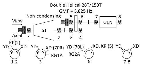
The machine train is a steam turbine-generator set that consists of a back pressure turbine, a reduction gear, and a 4-pole generator with a capacity of 12 MW. The turbine operating speed is 8196 rpm and it is connected to a 28-teeth pinion shaft that meshes with 153-teeth bull gear via a flexible coupling as depicted in Figure 1. Both turbine bearings are tilting pad journal bearings. Pinion bearings and gear bearings are offset and elliptical journal bearings, respectively. Thrust bearings are fitted on the non-drive end (NDE) side of the turbine and the NDE side of the gearbox’s low-speed shaft.
Each bearing of the unit, except the non-drive end bearings of the gearbox, is fitted with X-Y proximity probes for relative shaft vibration measurement (suffix XD/YD) as shown in Figure 1. An accelerometer is fitted horizontally on each drive end (DE) of the gearbox. Additionally, the unit is equipped with dual thrust position probes at the NDE of the turbine HP and the NDE of the gearbox’s low-speed shafts. Keyphaser probe is installed on the high and low-speed shafts. The shaft vibration alarm and trip setpoint of the turbine are 55 and 100 µmp-p, respectively.

Figure 1: Machine train diagram and transducers layout
Historical background
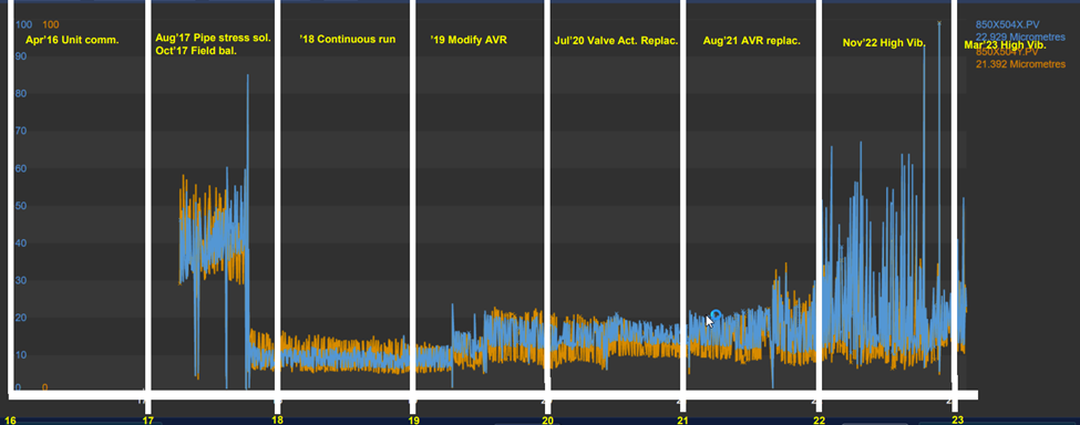
The machine was commissioned in 2016 and has never been overhauled since. According to the trend provided by the plant’s maintenance personnel, the high shaft vibration amplitudes of the LP turbine have occurred randomly since November 2022 as presented in Figure 2.

Figure 2: Trend of Bearing 2 XD/YD overall amplitudes since commissioning
Vibration data discussion
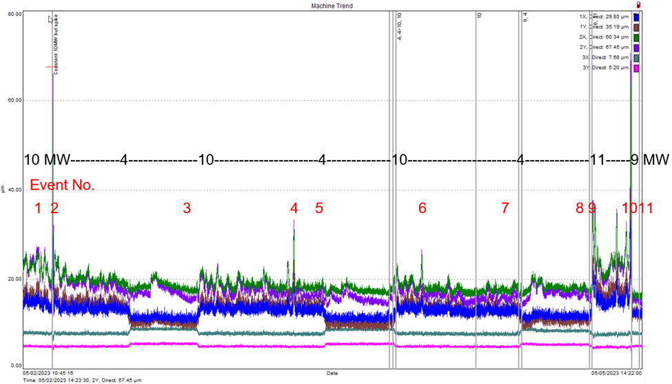
The trend plot of the direct shaft vibration amplitude of Bearing 1-3 XD/YD with MW and Event No labels is shown in Figure 3. It can be seen that high vibration amplitudes randomly occurred at Bearing 2 XD/YD when the unit was operated above 10 MW (indicated by Events No. 2, 4, 9, and 10). The comparison of shaft orbits, synchronous (1X) vibration vectors, and shaft centerline plots of Bearings 1 and 2 at 10 MW with low vibration amplitudes, 10 MW with high vibration amplitudes, and 9 MW with high vibration amplitudes are presented in Figure 4 to Figure 6, respectively. The loops in 1X polar plots and the shape of shaft orbits indicated rub-induced rotor bow. The significant shaft centerline movement at Bearing 1 indicated a pipe strain issue. However, the shaft centerline position at Bearing 2 during high and low vibration amplitude are not noticeably different which indicates that the randomly occurred rub-induced rotor bow at Bearing 2 was unlikely caused by casing thermal expansion/distortion but presumably caused by oil carbonization at the oil seal due to the random build-up and collapse of the carbonized oil or coke.

Figure 3: Trend of direct shaft vibration 1-3 XD/YD before remedy action

Figure 4: Direct shaft orbits, 1X polar plots, and shaft centerline plots of Bearings 1 and 2 at 10 MW (low Bearing 2 vibration amplitudes, event No.1 in Figure 2)

Figure 5: Direct shaft orbits, 1X polar plots, and shaft centerline plots of Bearings 1 and 2 at 10 MW (high Bearing 2 vibration amplitudes, event No.2 in Figure 2)

Figure 6: Direct shaft orbits, 1X polar plots, and shaft centerline plots of Bearings 1 and 2 at 9 MW (high Bearing 2 vibration amplitudes, event No.10 in Figure 2)
Remedy action and result
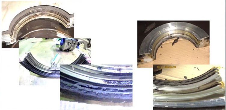
The following inspection revealed clear evidence of oil carbonization on the oil seal of Bearing 2 (LP) as shown in Figure 7. Also, the restrained inlet steam pipe support and misaligned exhaust steam pipe flange which are evidence of pipe strain issues, were found. The carbonized oil was cleaned and the seal gap was adjusted. The restrained inlet pipe support was also fixed but the misaligned exhaust flange was left as it was.

Figure 7: Oil carbonization at the oil seal of Bearing 2 (LP side) found during inspection (photos provided by the turbine maintenance company)
The trend plot of the direct shaft vibration amplitude of Bearing 1-3 XD/YD with MW after the maintenance is shown in Figure 8. The machine was able to reach the maximum output of around 12 MW without the amplitude spike. Note that the vibration amplitudes at the second 4 MW are lower than those of the first 4 MW due to the straightening of the rotor.

Figure 8: Trend of direct shaft vibration 1-3 XD/YD after remedy action
Conclusions
In this case, multiple plots were utilized to identify the separate root cause of vibration issues. and distinguish the source of the rub-induced rotor bow. The rub-induced bow from the carbonized oil seal can be recognized by the random spike in vibration amplitude at a constant speed that has the synchronous (1X) predominant frequency with the minimum change in average shaft centerline position, hence no significant change in the dynamic stiffness, during the occurrence of the rub. The knowledge of machine configuration and process is also valuable in identifying the possibility of carbonized oil seal. By fixing most of the root causes, the machine was able to operate at its maximum capacity without the hindrance from the vibration amplitude spike issue.

Comments